

A CO2 laser power supply does more than generate the high voltage required by a glass laser tube. It must also receive control signals from the laser machine, adjust the requested output level and respond to protection circuits.
Understanding these control functions is important when selecting a replacement power supply, connecting a machine controller or diagnosing a laser that does not fire correctly. Because terminal names and signal requirements may vary between models, the wiring diagram for the actual power supply must always be checked before making any connection.
What Does “Control Mode” Mean?
For a CO2 laser power supply, control mode can refer to two different aspects:
- External machine control: How the controller starts the laser, adjusts the requested power and enables protection circuits.
- Internal power regulation: How the power supply monitors and regulates its electrical output.
Machine manufacturers, installers and repair technicians usually need to focus first on external control compatibility. The internal regulation method is part of the power supply design and normally does not require adjustment by the machine operator.
Laser Trigger Control
The trigger signal tells the power supply when laser output is required.
Depending on the power supply model, triggering may use:
- An active-low control signal
- An active-high control signal
- A manual test input
- A controller-generated pulse signal
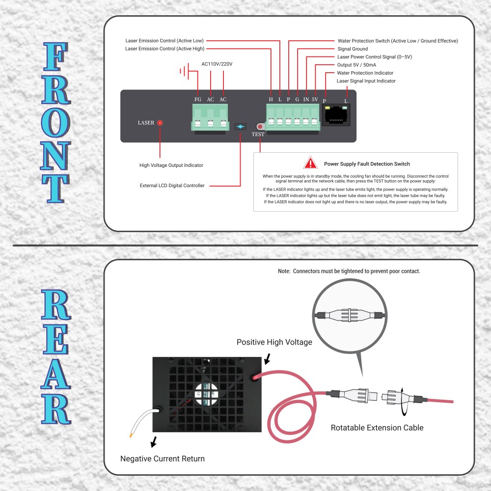
Terminals may be marked with letters such as L, H or TL, but the same letter does not necessarily have an identical definition on every power supply.
For example, one model may fire when its trigger input is connected to signal ground, while another may require a high-level control signal. Connecting the wrong signal may prevent the laser from firing or may create a risk of unexpected laser output.
Never identify the trigger method only from the terminal letters. Confirm the control logic from the label, terminal definition or wiring diagram for the specific model.
Laser Power Adjustment
The controller also sends a command that determines the requested laser output level. This power-control input is separate from the trigger signal.
Common methods include:
Analog Voltage Control
An analog control signal represents the requested laser power. As the control voltage changes within the range specified for the power supply, the requested output level changes accordingly.
The permitted signal range must be confirmed for the exact model. Applying an unsuitable voltage may cause incorrect operation or damage the control interface.
PWM Control
Pulse-width modulation, commonly called PWM, adjusts the requested output according to the duty cycle of a pulse signal.
The PWM signal level, frequency range and duty-cycle requirements depend on the power supply and machine controller. A PWM output should not be connected until both devices have been checked for compatibility.
Manual Potentiometer Control
Some laser machines use a manual potentiometer or control panel to set the requested power. The potentiometer is connected to the low-voltage reference, control input and signal-ground terminals according to the applicable wiring diagram.
Do not assume that the same potentiometer wiring can be transferred directly from one power supply model to another.
Trigger Control and Power Control Work Together
The trigger signal and power-control signal perform different functions:
- The trigger signal determines when the laser is allowed to fire.
- The power-control signal determines the requested output level.
A correct trigger signal without a valid power command may result in little or no laser output. A valid power command without a trigger signal will normally not start the laser.
When a laser tube does not fire, both signal types should be checked rather than replacing the power supply immediately.
Water-Protection and Interlock Control
A CO2 laser system normally includes a protection input connected to the cooling-water or safety-interlock circuit.
Depending on the model, this terminal may be marked P, WP or by another designation. Its purpose is to prevent laser output when the required protection condition is not satisfied.
The protection circuit may include:
- Water-flow monitoring
- Chiller alarm output
- Machine-cover interlock
- Emergency-stop circuit
- Other equipment safety controls
The exact arrangement depends on the complete laser machine.
Do not permanently bypass a water-protection or safety-interlock circuit to keep the laser operating. If the power supply does not enable laser output, check the cooling system, protection wiring and controller status before concluding that the power supply has failed.
Signal Ground and Protective Earth Are Different
The control terminals normally include a signal-ground connection used as a reference for low-voltage control signals.
Protective earth is used for electrical safety and is connected to the appropriate grounding terminal or enclosure according to the equipment documentation and applicable electrical requirements.
These two connections serve different purposes.
Do not connect protective earth, neutral and signal ground together simply because a terminal is marked with the letter G. Verify the complete terminal definition before wiring.
Manual Test Function
Some CO2 laser power supplies include a test button or a dedicated test input. This function may help a qualified technician determine whether the power supply and laser tube can produce output independently of the machine controller.
Before using a test function:
- Confirm that cooling water is circulating.
- Confirm that the laser path is controlled.
- Keep people away from the beam path.
- Check the high-voltage insulation.
- Use the test function only as described for the specific model.
- Apply only a short test command at an appropriate power setting.
- Keep the emergency-stop control accessible.
A successful manual test does not prove that all controller connections are correct. It only helps separate a possible power-stage problem from a control-signal or protection-circuit problem.
Do not short control terminals as a general test method. Incorrect test connections may cause unexpected laser firing or damage the control interface.
Internal Regulation of the Power Supply
Inside a laser power supply, feedback circuits monitor electrical conditions and adjust switching operation to maintain the required output.
Depending on the power-supply design, regulation may involve voltage feedback, current feedback or a combination of control methods. Compensation and protection circuits may also be used to maintain stability and respond to abnormal conditions.
These internal control methods are engineering characteristics rather than user-selectable operating modes. They should not be adjusted or repaired by opening the enclosure.
A CO2 laser power supply contains hazardous high voltage even after the machine has been switched off. Do not open the enclosure. Internal diagnosis and repair should only be performed by qualified personnel using appropriate procedures and equipment.
How to Check Controller Compatibility
Before installing a new or replacement power supply, compare the controller and power supply requirements.
Check:
- Trigger signal type
- Active-high or active-low logic
- Power-control method
- Permitted control-signal range
- PWM requirements, if applicable
- Signal-ground connection
- Water-protection input logic
- Manual test function
- Connector and terminal arrangement
- AC input voltage
- Laser tube power rating
Do not select a replacement only because the enclosure size and output cable appear similar. Electrical ratings and control interfaces may be different.
If the original wiring is still available, photograph the label and all terminal connections while the machine is switched off and disconnected from the AC supply.
Common Control Problems
The Laser Does Not Fire
Possible causes include:
- No trigger signal from the controller
- Incorrect active-high or active-low connection
- Open water-protection circuit
- Chiller alarm or insufficient water flow
- Missing signal-ground connection
- Incorrect controller settings
- Loose terminal wiring
- Power supply or laser tube fault
Check the signal and protection conditions before replacing parts.
The Laser Fires During a Manual Test but Not During Normal Operation
This often indicates that the power supply can produce output, while the controller signal, protection circuit or related wiring still requires inspection.
Check the trigger input, power-control signal, signal ground, controller configuration and water-protection status.
Laser Output Does Not Follow the Power Setting
Possible causes include:
- Incorrect analog or PWM connection
- Unsuitable control-signal range
- Incorrect PWM settings
- Poor signal-ground connection
- Controller configuration error
- Loose or damaged control wiring
- Power supply or laser tube condition
The indicated percentage on a machine control panel is a command value. It should not automatically be treated as a direct measurement of laser output or tube current.
The Laser Fires Unexpectedly
Stop the machine immediately if the laser fires without the intended command.
Possible causes include incorrect trigger logic, damaged wiring, an unsuitable controller connection or a fault in the control circuit. Disconnect the machine from the AC supply and arrange inspection by a qualified technician.
Do not continue testing while anyone is exposed to the laser beam path.
Safe Testing Procedure
Before checking control signals:
- Switch off and disconnect the machine.
- Follow the required waiting and discharge procedure.
- Confirm that the cooling system is ready.
- Inspect all external wiring.
- Verify terminal definitions.
- Keep the laser path enclosed or controlled.
- Use suitable measuring equipment.
- Avoid contact with high-voltage components.
- Do not open the power supply enclosure.
Control-signal measurements should be made only by personnel familiar with the equipment. Always use the documentation for the installed power supply and controller.
Information Needed for Control-Signal Support
When requesting technical support, provide:
- Laser power supply model
- Clear photo of the product label
- Laser tube rated power
- AC input voltage
- Machine controller model
- Photos of the control terminals
- Photos of the original wiring
- Trigger signal type, if known
- Power-control method, if known
- Cooling-system and protection status
- Description of the operating problem
- Relevant indicator or alarm information
Photos should be taken only while the machine is switched off and disconnected from the AC mains supply.
Need Help Matching a Laser Power Supply and Controller?
Jinan Zhenyu Electronics Co., Ltd. supplies CO2 laser power supplies for different glass laser tube power ratings and machine applications.
Send us the existing power supply model, laser tube power, input voltage, controller information and clear terminal photos. We can help check the basic control-interface and model-matching information before installation or replacement.